ARM assembler in Raspberry Pi – Chapter 3
We saw in chapter 1 and chapter 2 that we can move values to registers (using mov instruction) and add two registers (using add instruction). If our processor were only able to work on registers it would be rather limited.
Memory
A computer has a memory where code (.text in the assembler) and data are stored so there must be some way to access it from the processor. A bit of digression here, in 386 and x86-64 architectures, instructions can access registers or memory, so we could add two numbers, one of which is in memory. You cannot do this in ARM where all operands must be registers. We can work around this problem (not really a problem but a deliberate decision design that goes beyond the scope of this text) by loading data to a register from memory and storing data from a register to a memory.
These two special operations, loading and store, are instructions on their own called usually load and store. There are several ways to load and store data from/to memory but today we will focus on the simplest ones: load to register ldr and store from register str.
Loading data from memory is a bit complicated because we need to talk about addresses.
Addresses
To access data we need to give it a name. Otherwise we could not refer what piece of data we want. But of course a computer does not have a different name for every piece of data it can keep in memory. Well, in fact it does have a name for every piece of data. It is the address. The address is a number, in ARM a 32-bit number that identifies every byte (this is 8 bits) of the memory.
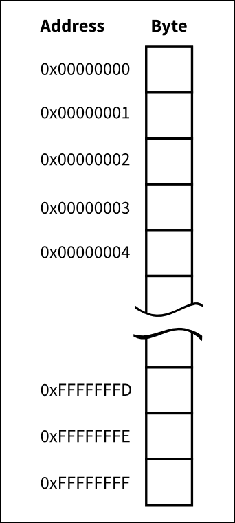 Memory is like an array of bytes where each byte has its own address.
When loading or storing data from/to memory we need to compute an address. This address can be computed in many ways. Each of this modes is called an addressing mode. ARM has several of these addressing modes and it would took a while to explain them all here, so we will consider just one: addressing through a register.
It is not by chance that ARM has integer registers of 32 bits and the addresses of the memory are 32 bit numbers. This means that we can keep an address inside a register. Once we have an address inside a register, we can use that register to load or store some piece of data.
Data
We saw in the chapter 1 that the assembler contains both code (called text) and data. I was deliberately loose when describing labels of the assembler. Now we can unveil their deep meaning: labels in the assembler are just symbolic names to addresses in your program. These addresses may refer both to data or code. So far we have used only one label main to designate the address of our main function. A label only denotes an address, never its contents. Bear this in mind.
I said that assembler is a thin layer on top of the binary code. Well, that thin layer may now look to you a bit thicker since the assembler tool (as) is left responsible of assigning values to the addresses of the labels. This way we can use these labels and the assembler will do some magic to make it work.
So, we can define data and attach some label to its address. It is up to us, as assembler programmers, to ensure the storage referenced by the label has the appropiate size and value.
Let's define a 4 byte variable and initialize it to 3. We will give it a label myvar1.
.balign 4
myvar1:
    .word 3
There are two new assembler directives in the example above: .balign and .word. When as encounters a .balign directive, it ensures the next address will start a 4-byte boundary. This is, the address of the next datum emitted (i.e. an instruction but it could be data as well) will be a multiple of 4 bytes. This is important because ARM imposes some restrictions about the addresses of the data you may work. This directive does nothing if the address was already aligned to 4. Otherwise the assembler tool will emit some padding bytes, which are not used at all by the program, so the alignment requested is fulfilled. It is possible that we could omit this directive if all the entities emitted by the assembler are 4 byte wide (4 bytes is 32 bits), but as soon as we want to use differently sized data this directive will become mandatory.
Now we define the address of myvar1. Thanks to the previous .balign directive, we know its address will be 4 byte aligned.
.word directive states that the assembler tool should emit the value of the argument of the directive as a 4 byte integer. In this case it will emit 4 bytes containing the value 3. Note that we rely on the fact that .word emits 4 bytes to define the size of our data.
Sections
Data lives in memory like code but due to some practical technicalities, that we do not care very much now, it is usually kept together in what is called a data section. .data directive tells the assembler to emit the entities in the data section. That .text directive we saw in the first chapter, makes a similar thing for code. So we will put data after a .data directive and code after a .text.
Load
Ok, we will retrieve our example from the Chapter 2 and enhance it with some accesses to memory. We will define two 4 byte variables myvar1 and myvar2, initialized to 3 and 4 respectively. We will load their values using ldr, and perform an addition. The resulting error code should be 7, like that of chapter 2.
1
2
3
4
5
6
7
8
9
10
11
12
13
14
15
16
17
18
19
20
21
22
23
24
25
26
27
28
29
30
31
32
33
34
35
36
/* -- load01.s */

/* -- Data section */
.data

/* Ensure variable is 4-byte aligned */
.balign 4
/* Define storage for myvar1 */
myvar1:
    /* Contents of myvar1 is just 4 bytes containing value '3' */
    .word 3

/* Ensure variable is 4-byte aligned */
.balign 4
/* Define storage for myvar2 */
myvar2:
    /* Contents of myvar2 is just 4 bytes containing value '4' */
    .word 4

/* -- Code section */
.text

/* Ensure code is 4 byte aligned */
.balign 4
.global main
main:
    ldr r1, addr_of_myvar1 /* r1 ← &myvar1 */
    ldr r1, [r1]           /* r1 ← *r1 */
    ldr r2, addr_of_myvar2 /* r2 ← &myvar2 */
    ldr r2, [r2]           /* r2 ← *r2 */
    add r0, r1, r2         /* r0 ← r1 + r2 */
    bx lr

/* Labels needed to access data */
addr_of_myvar1 : .word myvar1
addr_of_myvar2 : .word myvar2
I have cheated a bit in the example above because of limitations in the assembler. As you can see there are four ldr instructions. I will try to explain their meaning. First, though, we have to discuss the following two labels.
34
35
36
/* Labels needed to access data */
addr_of_myvar1 : .word myvar1
addr_of_myvar2 : .word myvar2
Well, these two labels, contain the address of myvar1 and myvar2. You may be wondering why we need them if we already have the address of our data in labels myvar1 and myvar2. Well a detailed explanation is a bit long, but what happens here is that myvar1 and myvar2 are in a different section: in the .data section. That section exists so the program can modify it, this is why variables are kept there. On the other hand, code is not usually modified by the program (for efficiency and for security reasons). So this is a reason to have two different sections with different properties attached to them. But, we cannot directly access a symbol from one section to another one. Thus, we need a special label in .code which refers to the address of an entity in .data section.
Well, when the assembler emits the binary code, .word myvar1 will not be address of myvar1 but instead it will be a relocation. A relocation is the way the assembler uses to emit an address, the exact value of which is unknown but it will known be when the program is linked (i.e. when generating the final executable). It is like saying well, I have no idea where this variable will actually be, let's the linker patch this value for me later
. So this addr_of_myvar1 will be used instead. The address of addr_of_myvar1 is in the same section .text. That value will be patched by the linker during the linking phase (when the final executable is created and it knows where all the entities of our program will definitely be laid out in memory). This is why the linker (invoked internally by gcc) is called ld. It stands for Link eDitor.
27
28
    ldr r1, addr_of_myvar1 /* r1 ← &myvar1 */
    ldr r1, [r1]           /* r1 ← *r1 */
Ok, so two loads. The first one in line 27 actually loads the relocation value of the address of myvar1. This is, there is some data in memory, the address of which is addr_of_myvar1, with a size of 4 bytes containing the real address of myvar1. So after the first ldr, in r1 we have the real address of myvar1. But we do not want the address at all, but the contents of the memory at that address, thus we do a second ldr.
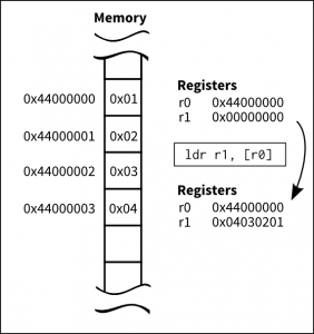 Assuming the given memory contents, this is what happens to registers after a load instruction is executed.
Probably you are wondering why the two loads have different syntax. The first ldr uses the symbolic address of addr_of_myvar1 label. The second ldr uses the value of the register as the addressing mode. So, in the second case we are using the value inside r1 as the address. In the first case, we do not actually know what the assembler uses as the addressing mode, so we will ignore it for now.
The program loads two 32 bit values from myvar1 and myvar2, that had initial values 3 and 4, adds them and sets the result of the addition as the error code of the program in the r0 register just before leaving main.
$ ./load01 ; echo $?
7
Store
Now take the previous example but instead of setting the initial values of myvar1 and myvar2 to 3 and 4 respectively, set both to 0. We will reuse the existing code but we will prepend some assembler to store a 3 and a 4 in the variables.
1
2
3
4
5
6
7
8
9
10
11
12
13
14
15
16
17
18
19
20
21
22
23
24
25
26
27
28
29
30
31
32
33
34
35
36
37
38
39
40
41
42
43
44
/* -- store01.s */

/* -- Data section */
.data

/* Ensure variable is 4-byte aligned */
.balign 4
/* Define storage for myvar1 */
myvar1:
    /* Contents of myvar1 is just '3' */
    .word 0

/* Ensure variable is 4-byte aligned */
.balign 4
/* Define storage for myvar2 */
myvar2:
    /* Contents of myvar2 is just '3' */
    .word 0

/* -- Code section */
.text

/* Ensure function section starts 4 byte aligned */
.balign 4
.global main
main:
    ldr r1, addr_of_myvar1 /* r1 ← &myvar1 */
    mov r3, #3             /* r3 ← 3 */
    str r3, [r1]           /* *r1 ← r3 */
    ldr r2, addr_of_myvar2 /* r2 ← &myvar2 */
    mov r3, #4             /* r3 ← 4 */
    str r3, [r2]           /* *r2 ← r3 */

    /* Same instructions as above */
    ldr r1, addr_of_myvar1 /* r1 ← &myvar1 */
    ldr r1, [r1]           /* r1 ← *r1 */
    ldr r2, addr_of_myvar2 /* r2 ← &myvar2 */
    ldr r2, [r2]           /* r2 ← *r2 */
    add r0, r1, r2
    bx lr

/* Labels needed to access data */
addr_of_myvar1 : .word myvar1
addr_of_myvar2 : .word myvar2
Note an oddity in the str instruction, the destination operand of the instruction is not the first operand. Instead the first operand is the source register and the second operand is the addressing mode.
$ ./store01; echo $?
7
That's all for today.